Case study · Independent
Printing parts I never modelled
I design functional 3D-printed parts by describing them to Claude, which writes the geometry, then go straight to my printer. No CAD modelling by hand.
- Role
- Designer and maker, solo, with AI
- Organization
- Independent
- Tools
- Claude, AI-written CAD code, Bambu Studio, Bambu printer
In short
- 01Building and fixing things around the house keeps needing small parts nobody sells: a mount, a jig, a cover.
- 02Instead of modelling them, I describe the part, its measurements and how it should fit. The AI writes the geometry and exports a file I can print.
- 03I print, test the fit and tell the AI what was off. The version numbers in the file names are that loop, written down.
- problem framing
- describing parts in words · measurements and fit
- AI-written geometry · code, not hand modelling
- fit testing
- 3D printing · Bambu Studio
01Problem
The model took longer than the print
A lot of what I need to print is for building work: cabinet jigs, mounts, covers. Each part fits one pipe or one panel, so there is nothing to buy.
Modelling each one by hand was the slow part. I know what the part needs to do and what it needs to fit. I wanted to say that and print the result.
02The loop
Describe it, print it, say what was off
I start with the job and the numbers: what the part holds, what it fits around, the measurements I took. The AI writes the part as code and exports an STL. I check it in a 3D viewer, slice it in Bambu Studio and print it.
Then I test the fit and describe what was wrong, in plain words. The AI changes the code and I print the next version. I never open a modelling timeline.
03Downspout mount
51 versions of one camera mount
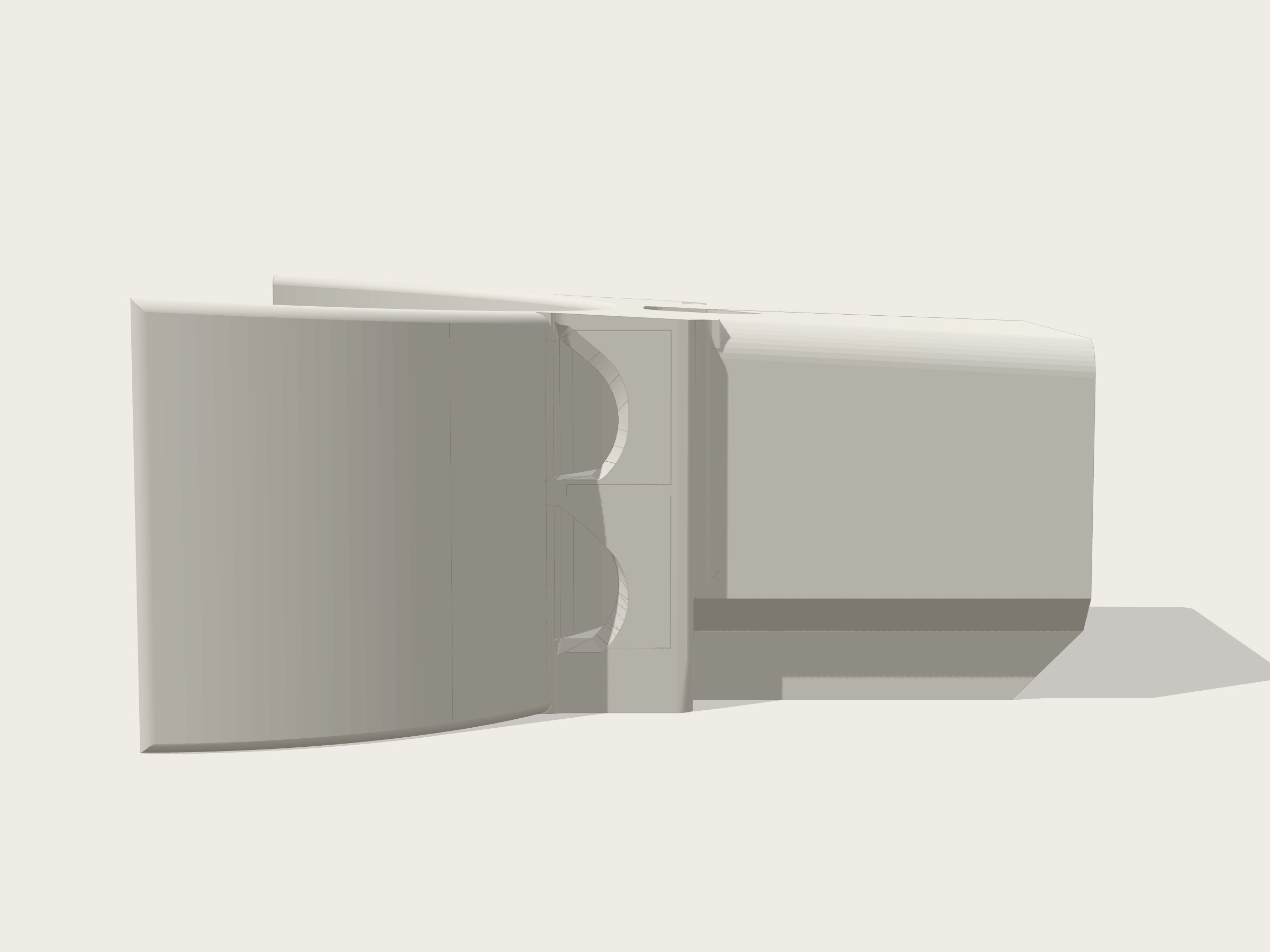
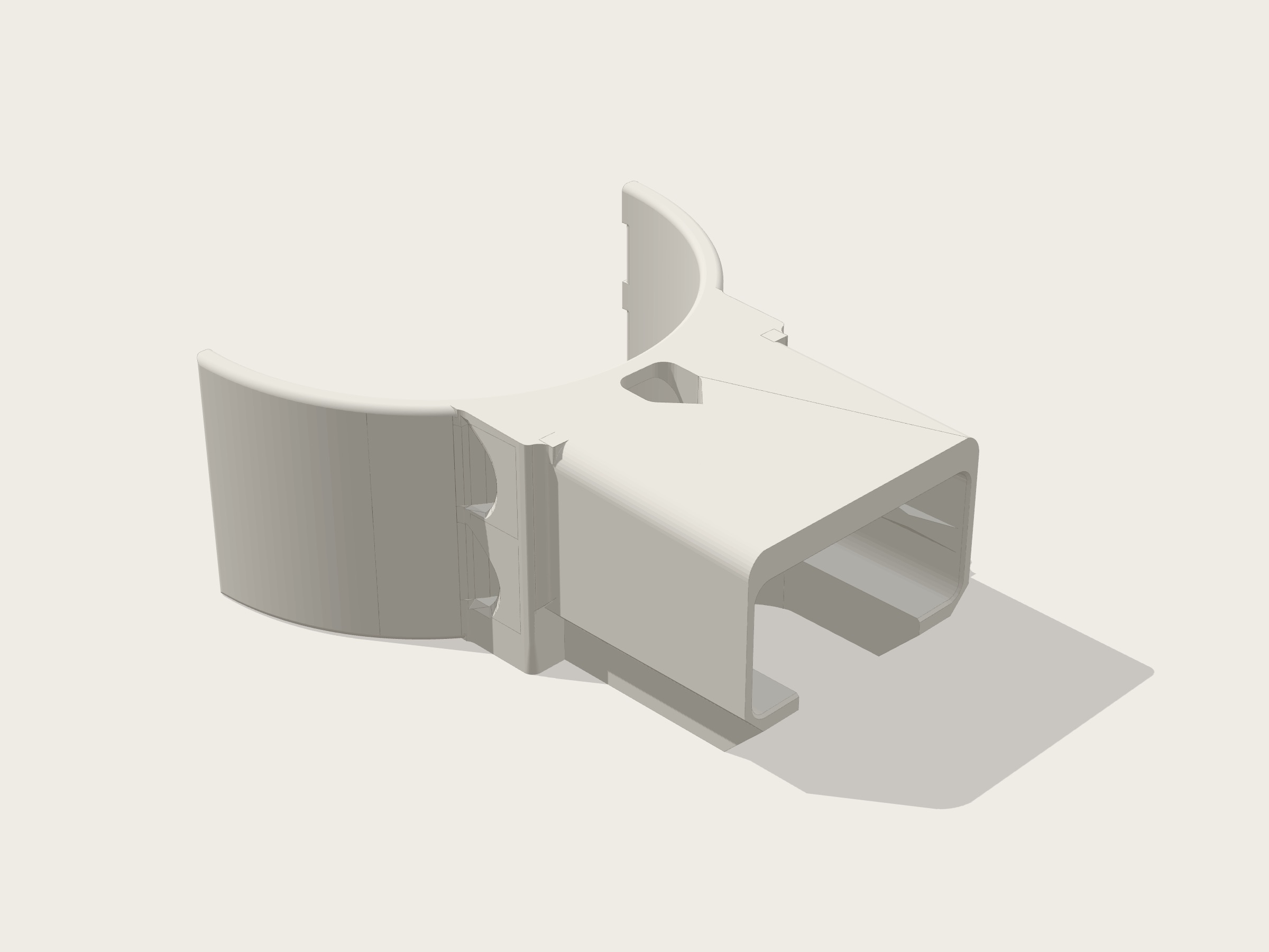
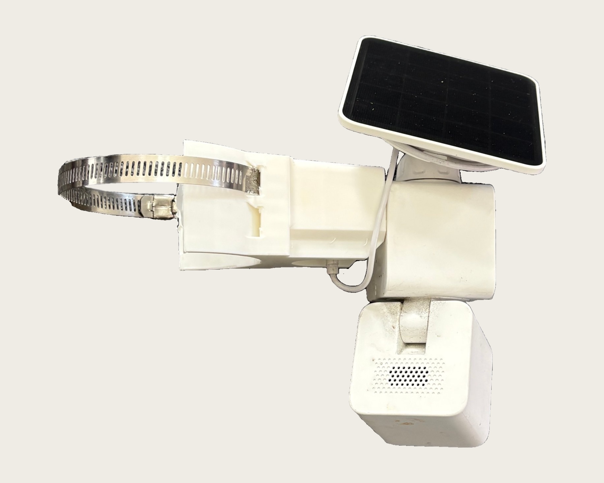
I wanted a solar pan camera on a round downspout, held by a stainless hose clamp. The mount is one piece: a saddle that wraps the pipe, slots for the clamp band, a socket the camera snaps into, and a pass-through for the charging cable.
The 4-inch version reached v51, and a 3-inch variant followed. Each new version started as a sentence to the AI, not an evening in CAD. It printed, and the camera and solar panel went on it.
04Cabinet jig
From a corner template to a lighter jig
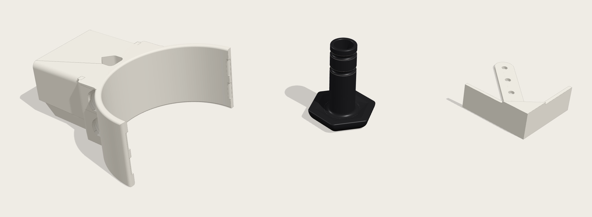
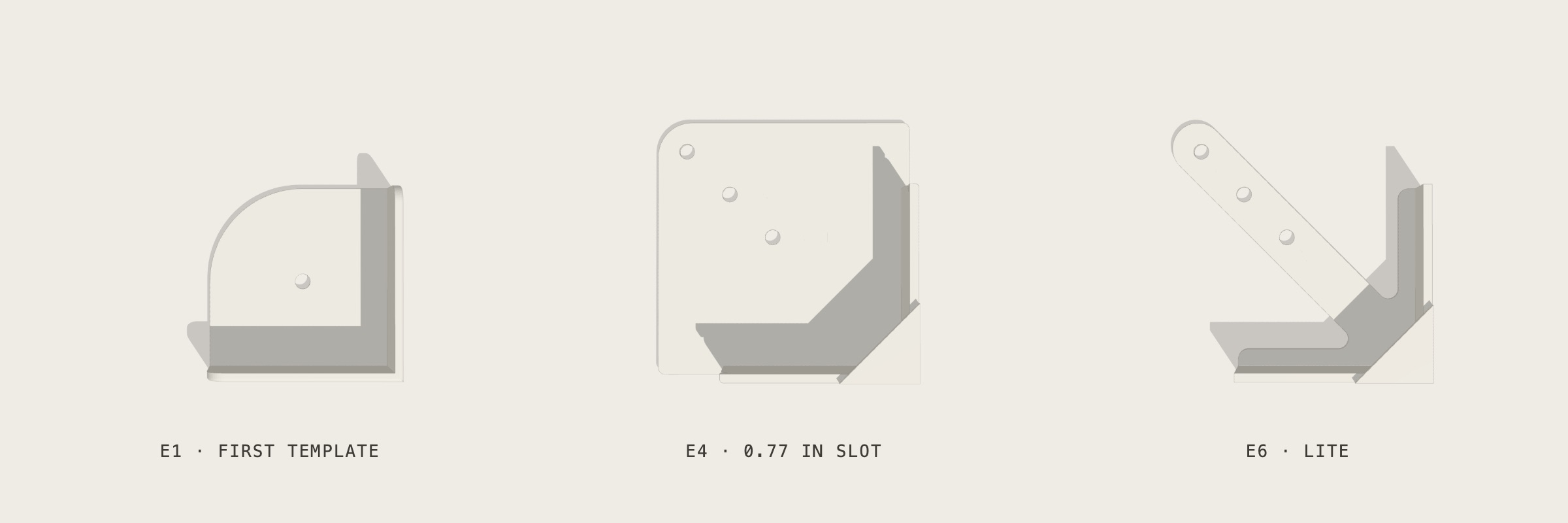
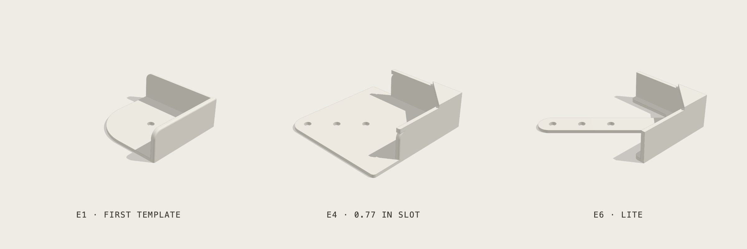
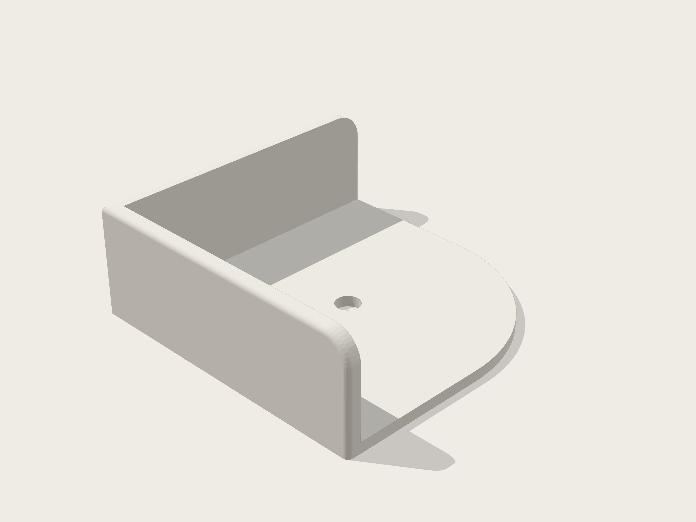
For IKEA Besta and Sektion cabinets I needed holes in the same place on every panel. The first file was a small corner template: a plate with one hole and two walls that hook over the corner of a panel.
Later files grew the plate, added a row of three holes on the diagonal and a slot. The LITE version keeps the corner and the three holes and cuts the rest of the plate away. It uses a little over half the plastic of the version before it.
05Tee cover
Starting over from an earlier version
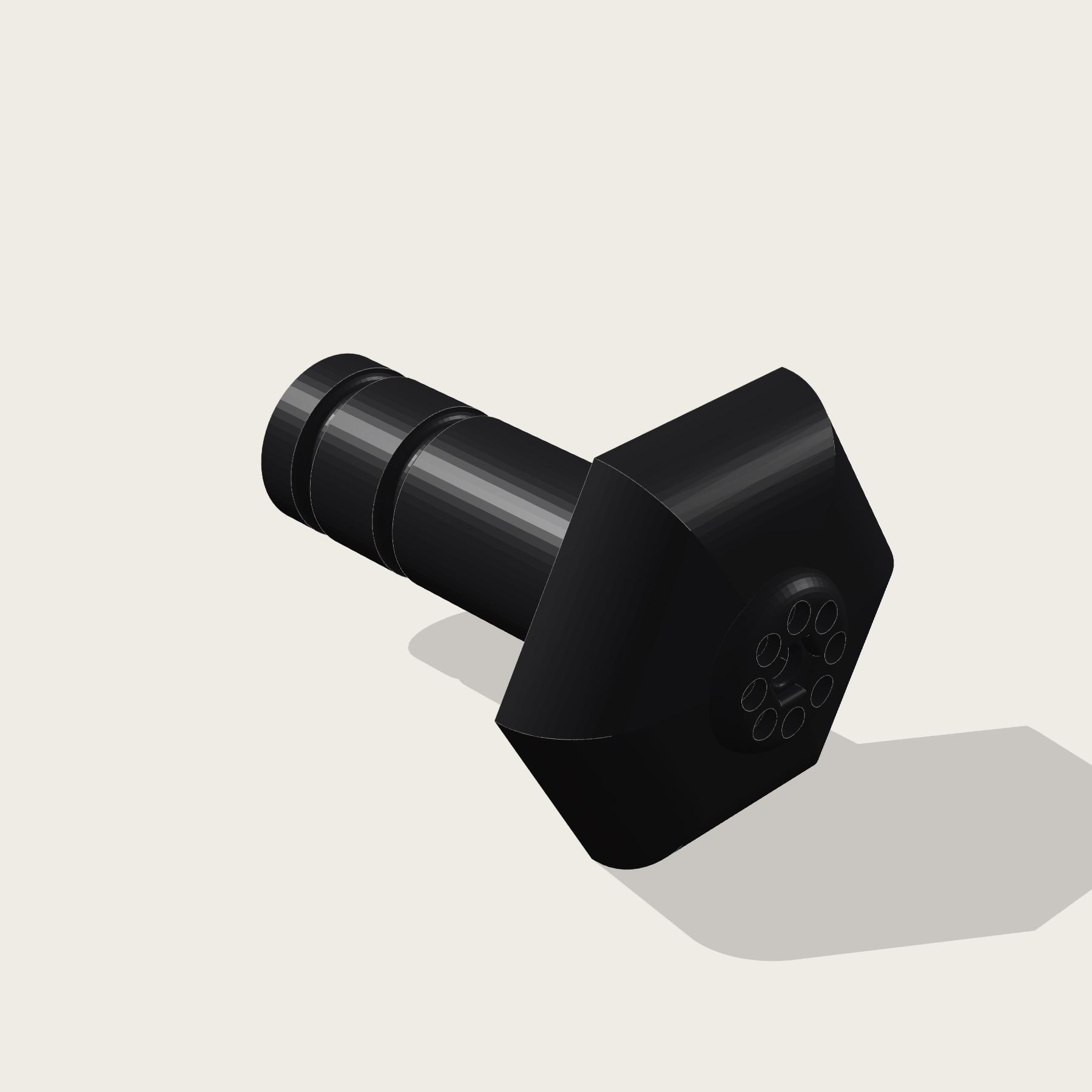
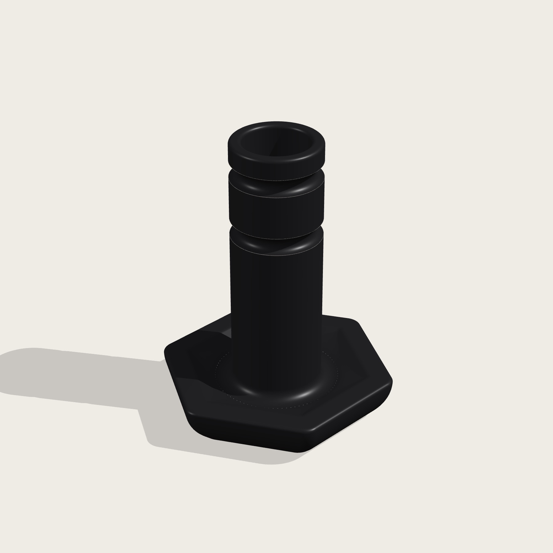
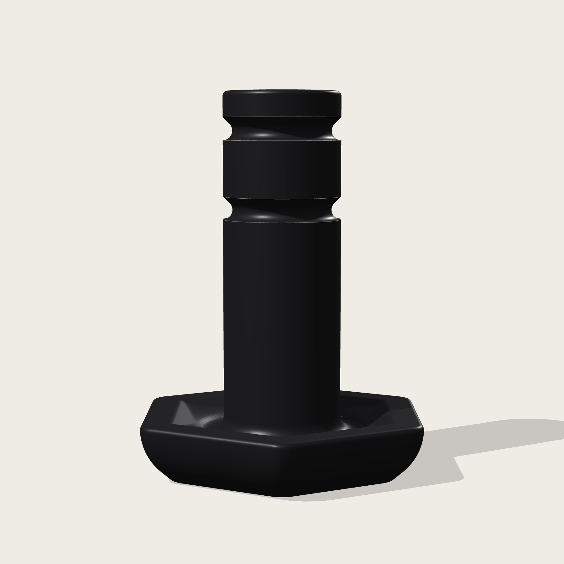
A cover for a hex tee fitting has an earlier version and a later one, and they look like different parts. The earlier one is a hex body with a long grooved pin coming out of one face.
The later one, v13, is a hex base with a raised rim and a hollow post with two grooves. Same job, a new shape.
06What I learned
Fit is the design work
The AI gets the shape close on the first try. What takes versions is fit: clearance around a pipe, a slot a clamp band can start into, a corner that sits square on a panel. That knowledge comes from holding the print, so the loop has to be fast.
It also changes what I bother to fix. A small change I would never remodel by hand now costs one message and one print.